Step 1 Add Input
Step | Description |
|---|---|
1 | Add Input |
2 | |
3 |
To create an input:
In the sidebar click Streaming.
Click the Inputs tab.
Click the Add Input button and the Add Input dialog opens.
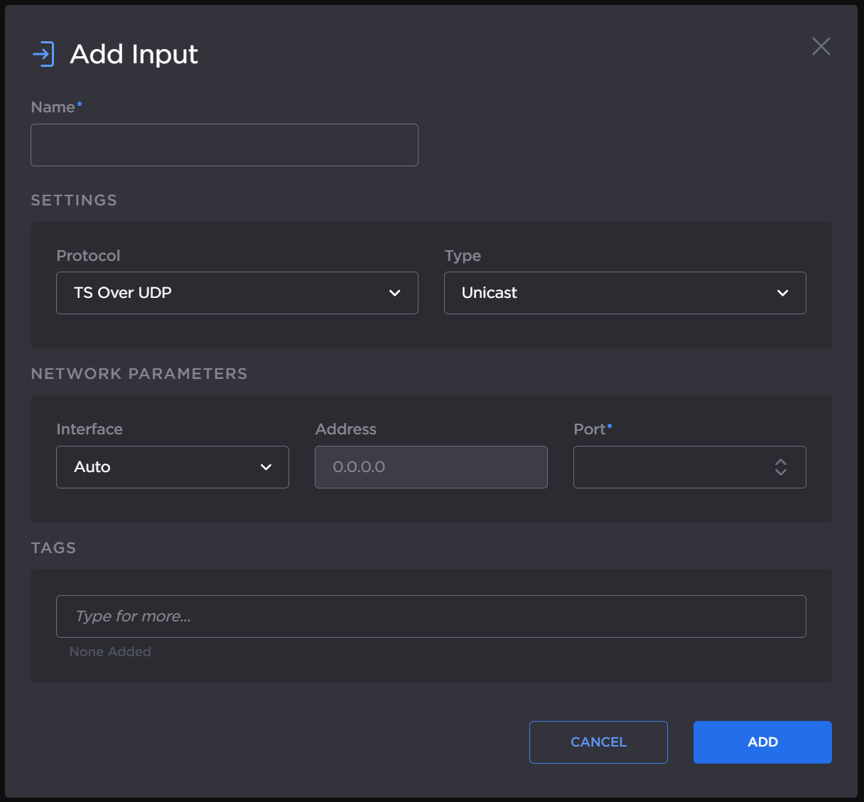
Add Input dialog
Enter a name for the input.
Select the desired protocol from the Protocol dropdown.
Enter the settings as desired. The available configuration options depend on the selected input streaming protocol.
The following figure shows the available settings in the Add Input dialog for a TS over UDP route. The numbered callouts in the figure indicate the step number in this procedure.
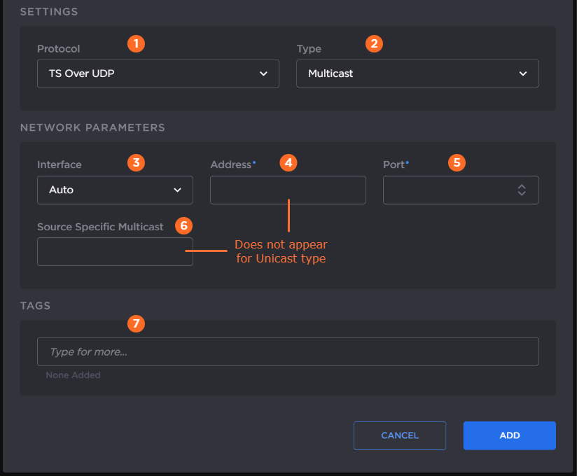
In the Protocol dropdown, select TS over UDP.
Select Unicast or Multicast in the Type dropdown.
Choose the desired network interface to use for this route in the dropdown. Available options depend on the hardware configuration.
If you chose Multicast in step 2, enter the multicast IP address.
Enter listening port number.
If you chose Multicast in step 2, optionally, enter the IGMP v3 source address in the Source Specific Multicast field.
Note
IGMPv3 Source Specific Multicast reception allows input streams to join a multicast group and filter the input streams based on a specific source IP address. Only streams originating from the specified source IP are forwarded to HMG/HSG, which allows HMG/HSG to quickly and easily select an input stream in environments with many sources sharing a common multicast IP. See IETF RFC 3376 for more details.
Optionally, assign tags to the input to help organize the Inputs list.
Continue to Step 2 Add Output.
The following figure shows the available settings in the Add Input dialog for a TS over SRT route. The numbered callouts in the figure indicate the step number in this procedure.
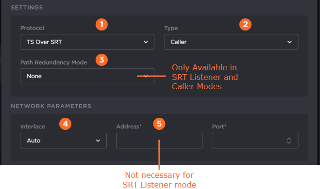
In the Protocol dropdown, select TS over SRT.
Specify the SRT connection mode in the Mode dropdown:
Caller — The SRT stream acts like a client and connects to a server listening and waiting for an incoming call.
Listener — The SRT stream acts like a server and listens and waits for clients to connect to it.
Rendezvous — Allows calling and listening at the same time.
Tip
To simplify firewall traversal, Rendezvous mode allows the encoder and decoder to traverse some firewall configurations without the need for IT to open a port.
If you chose Caller or Listener mode, select whether to use SRT Path Redundancy. If so, select the desired mode and use the +/– buttons next to each network address to add/subtract network paths when completing the following two steps. See Using Path Redundancy with SRT Streaming for more details.
Any (SRT Listener only) — Automatically use the path redundancy mode defined by SRT Caller.
Active-Active — Stream packets are sent on all defined network paths. The listener uses the first received stream packets and ignores the duplicate packets received from the other network paths. This mode maintains low latency at the expense of network bandwidth.
Active-Backup — Stream packets are sent only on the main network path. If the main path fails, one of the backup paths begins transmission of the stream. This mode saves network bandwidth at the expense of latency.
None — SRT Path Redundancy disabled.
Choose the desired Network Interface to use in the dropdown. Available settings depend on the hardware configuration.
If using SRT Listener mode, enter the listening port.
If using SRT Caller or Rendezvous mode, enter the input stream address and port.
SRT Parameters
In the SRT Parameters section of the Add Input dialog:
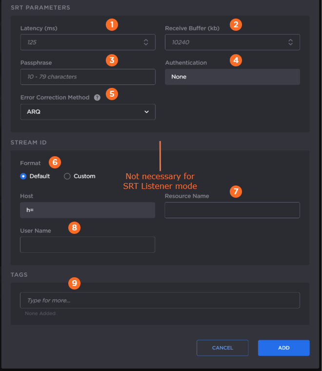
Enter the desired latency. This specifies the SRT receiver buffer that permits lost packet recovery. The size of this buffer adds to the total end-to-end latency. It is recommended to use a value that is at least 3 times the round-trip-time (RTT). Range = 20–8000 ms.
Note
Latency is for the SRT protocol only and does not include the capture, encoding, decoding, and display processes of the endpoint devices.
(For advanced users only.) Enter the desired Receive Buffer Size. High-bandwidth (≥60 Mbps), high-latency streams may experience video dropouts due to the default receive buffer size. If you notice this issue for your stream, use the following formulas to guide you in setting an appropriate buffer size, where:
MTU size is defined at the stream's input.
Bitrate and negotiated latency are found on the route statistics page while the route is running. (See Viewing a Route’s Statistics.) The negotiated latency is not necessarily the value set in Step #2.
MTU Size | Suggested Receiver Buffer Size (in kByte) |
|---|---|
1000–1500 | (Bitrate in kbps ÷ 8) × negotiated latency in seconds × 1.5 |
750–1000 | (Bitrate in kbps ÷ 8) × negotiated latency in seconds × 1.7 |
< 750 | (Bitrate in kbps ÷ 8) × negotiated latency in seconds × 2.0 |
If using Encryption on any outputs, enter the desired passphrase to protect the stream. Must be between 10 to 79 UTF8 characters.
If you have entered an encryption passphrase in the previous step, you may optionally choose Authenticated Encryption Associated Data (AEAD) mode in the Authentication dropdown by selecting AES-GCM.
For SRT Listener mode, by default Auto is selected, which will connect to a peer no matter if the peer is configured for AES-GCM or not.
For Caller and Rendezvous modes, if AES-CTR is desired, select None at both peers. If AEAD mode is desired, select AES-GCM at both peers for the connection to succeed.
In SRT Caller mode with Path Redundancy disabled, select the Error Correction Method: ARQ (Automatic Repeat Request), FEC, or FEC+ARQ. See Choosing an Error Correction Method for SRT Streams for more information on using SRT FEC.
When FEC or FEC+ARQ is selected:Select the Layout: Even or Staircase.
Enter the number of rows and columns in the FEC matrix.
If you have a Haivision SRT Gateway, for SRT Caller mode in the Stream ID section. Select the desired Stream ID format.
If Default Stream ID format is selected, enter the Resource Name and User Name. The resulting Stream ID appears in the textbox below.
If Custom Stream ID format is selected, enter the desired text string for the Stream ID.
Optionally, assign tags to the input to help organize the Inputs list.
Click the Add button.
Continue to Step 2 Add Output.
The following figure shows the available settings in the Add Input dialog for a TS over RTP route. The numbered callouts in the figure indicate the step number in this procedure.
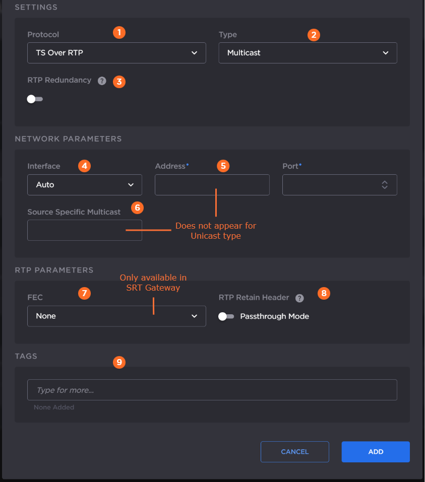
In the Protocol dropdown, select TS over RTP.
Select Unicast or Multicast in the Type dropdown.
If SMPTE 2022-7 support is desired:
Toggle RTP Redundancy to ON.
Select the RTP Receiver Class in the dropdown.
Use the Add button in the Network Parameters section to add additional network paths when completing the following step. When 3 or more addresses are visible, use the
 icon to remove network paths as desired.
Choose the desired network interface to use for this route in the dropdown. Available options depend on the hardware configuration.
Note
Auto mode is not supported in RTP multicast when RTP Redundancy is enabled.
If you chose Unicast in a previous step, enter the listening port number.
If you chose Multicast in a previous step, enter the multicast IP address and listening port number.
Tip
An even-numbered port is required for RTP, as recommended in RFC 3550. (The next odd-numbered port is typically reserved for RTCP messages.)
If you chose Multicast in a previous step, optionally, enter the IGMP v3 source address in the Source Specific Multicast field.
Note
IGMPv3 Source Specific Multicast reception allows input streams to join a multicast group and filter the input streams based on a specific source IP address. Only streams originating from the specified source IP are forwarded to HMG/HSG, which allows HMG/HSG to quickly and easily select an input stream in environments with many sources sharing a common multicast IP. See IETF RFC 3376 for more details.
If you are using a Haivision SRT Gateway, select whether PRO-MPEG FEC is enabled or not.
If you plan to tunnel the RTP stream through SRT, enable the Retain Header > Passthrough mode toggle. See Tunnelling an RTP Stream Through SRT for more details.
Note
This option is not supported when RTP Redundancy is enabled.
PRO-MPEG FEC is not supported when Passthrough mode is enabled.
Optionally, assign tags to the input to help organize the Inputs list.
Continue to Step 2 Add Output.
The following figure shows the available settings in the Add Input dialog for an RTMP route. The numbered callouts in the figure indicate the step number in this procedure.
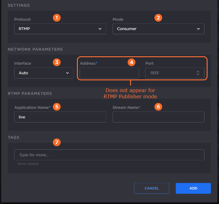
In the Protocol dropdown, select RTMP.
Select the mode for connection to the RTMP stream:
Consumer — Stream available for Media Gateway/SRT Gateway to access on an RTMP server.
Publisher — Stream sent directly to the Media Gateway/SRT Gateway's IP address. See Connecting an RTMP Publisher Source for further details regarding RTMP Publisher mode.
Choose the desired network interface to use for this route in the dropdown. Available options depend on the hardware configuration
If using RTMP Consumer mode, enter the input stream address and the port number.
Enter the RTMP application name, default “live”.
Enter the RTMP stream name.
Optionally, assign tags to the input to help organize the Inputs list.
Continue to Step 2 Add Output.
The following figure shows the available settings in the Add Input dialog for an RTSP route. The numbered callouts in the figure indicate the step number in this procedure.
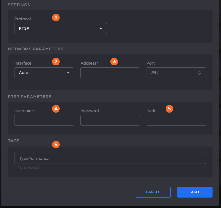
In the Protocol dropdown, select RTSP.
Choose the desired network interface to use for this route in the dropdown. Available options depend on the hardware configuration.
Enter the input stream address and the port number.
Specify the username and password for the RTSP stream.
Note
Depending on the stream, the username/password may not be required.
Enter the URL path of the RTSP stream
Optionally, assign tags to the input to help organize the Inputs list.
Continue to Step 2 Add Output.