Step 2 Add Output
Step | Description |
|---|---|
1 | |
2 | Add Output |
3 |
To create an output:
In the sidebar click Streaming.
Click the Outputs tab.
Click the Add Output button and the Add Output dialog opens.
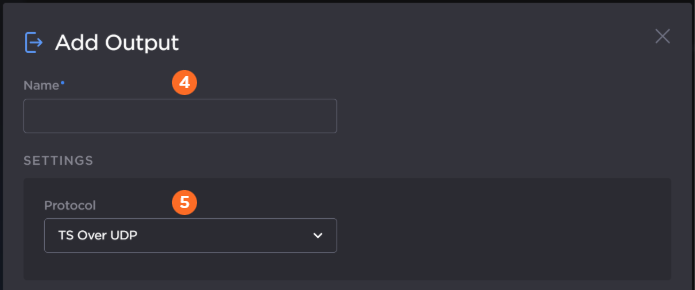
Enter a name for the output.
Select the desired protocol from the Protocol dropdown.
Enter the settings as desired. The available configuration options depend on the selected streaming protocol.
The following figure shows the available settings in the Add Output dialog for a TS over UDP output. The numbered callouts in the figure indicate the step number in this procedure.
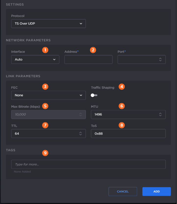
Select the desired network interface to use for the output in the dropdown. Available options depend on the hardware configuration.
Enter the output address and port number.
Enable or disable Forward Error Correction (FEC).
Note
VF FEC is a proprietary FEC and is not inter-operable with devices outside of the Haivision family.
Enable or disable Traffic Shaping for the stream. For some limited networks, such as satellites or some dedicated network pipes, it may be necessary to enable Traffic Shaping to smooth the traffic and respect the absolute upper limit configured. Traffic Shaping controls the outgoing stream so that the inter-packet time is constrained, to reduce the probability that TCP packets are dropped in a session.
Tip
Enabling Traffic Shaping does not dynamically modify the video encoder bitrate.
If traffic shaping is enabled in the previous step, enter the Maximum Bitrate in kbps.
Enter value for MTU (Maximum Transmission Unit) — The maximum allowed size of IP packets for the outgoing data stream. Range: 280-1500.
Enter value for TTL (Time-to Live for stream packets) — The number of router hops the stream packet is allowed to travel/pass before it must be discarded. Range: 1-255.
Enter value for ToS (Type of Service) — This value will be assigned to the Type of Service field of the IP Header for the outgoing streams. Range: 0x00-0xFF.
Optionally, assign tags to the output to help organize the Outputs list.
Click the Add button.
Important
The Gateway 100 Generation 2 appliance is not capable of sending a single 50-Mbps MPEG-TS input to two SRT outputs simultaneously (i.e., two 50-Mbps streams for 100-Mbps total output).
The following figure shows the available settings in the Add Output dialog for a TS over SRT output. The numbered callouts in the figure indicate the step number in this procedure.
SRT Caller | SRT Listener and Rendezvous |
|---|---|
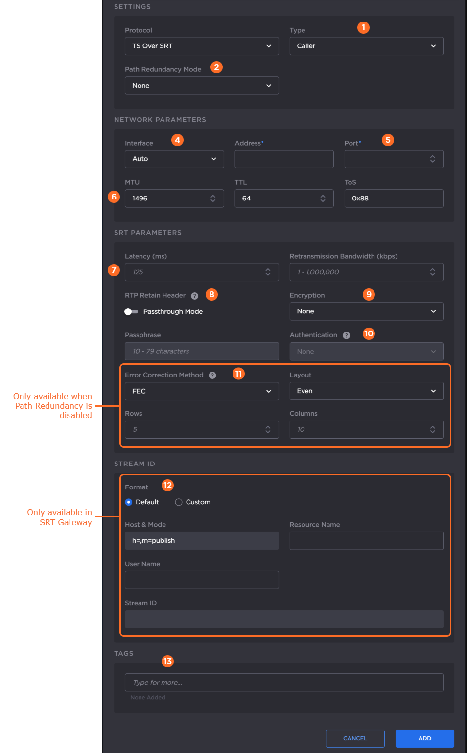 | 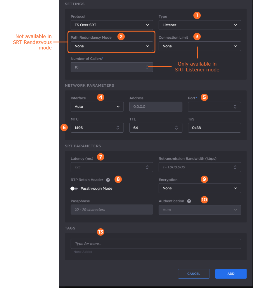 |
Select the SRT mode: Listener, Caller, or Rendezvous.
If you chose Caller or Listener mode, select whether to use SRT Path Redundancy. If so, select the desired mode and use the +/– buttons next to each network address to add/subtract network paths when completing the following three steps. See Using Path Redundancy with SRT Streaming for more details.
If you chose Listener mode, select whether that you would like a Caller connection limit. Use a limit if you are concerned about bandwidth consumption for your route.
Select the desired network interface to use for the output in the dropdown. Available options depend on the hardware configuration.
If you selected Listener mode, enter the listening port number.
If you selected Caller or Rendezvous mode, enter the output address and port number.Enter values for MTU, TTL, and ToS:
MTU (Maximum Transmission Unit) — The maximum allowed size of IP packets for the outgoing data stream. Range: 280-1500.
TTL (Time-to Live for stream packets) — The number of router hops the stream packet is allowed to travel/pass before it must be discarded. Range: 1-255.
ToS (Type of Service) — This value will be assigned to the Type of Service field of the IP Header for the outgoing streams. Range: 0x00-0xFF.
In the SRT Parameters section, enter the values for Latency and Retransmission Bandwidth:
Latency — The buffer size available for managing SRT packets. It is recommended to use a value that is at least 3 times the round-trip-time (RTT). Range = 20-8000 ms.
Note
Latency applies to the SRT protocol only and does not include the capture, encoding, decoding and display processes of the end-point devices.
Retransmission Bandwidth — Additional bandwidth that is used to accommodate recovery of lost packets, including the SRT header.
Note
We recommend using a value equal to 25% of your input stream’s bitrate. The value entered in this field is rounded up to the nearest byte value, so you may see a difference in the SRT statistics.
If you plan to tunnel an RTP stream through SRT and your input RTP stream has its respective Passthrough Mode toggle enabled, enable the Passthrough Mode toggle to transfer RTP headers through this SRT output. See Tunnelling an RTP Stream Through SRT for more details.
Enable or disable AE128 or AE256 encryption. If enabled, enter the passphrase.
If encryption is enabled in the previous step, optionally enable SRT Authenticated Encryption with Associated Data (AEAD) mode in the Authentication dropdown by selecting AES-GCM. For SRT Listener mode, by default Auto is selected, which will connect to a peer no matter if the peer is configured for AES-GCM or not. For Caller and Rendezvous modes, if AES-CTR is desired, select None at both peers. If AEAD mode is desired, select AES-GCM at both peers for the connection to succeed.
If you chose SRT Caller mode and Path Redundancy is disabled, select the Error Correction Method: ARQ, FEC, or FEC+ARQ. See Choosing an Error Correction Method for SRT Streams for more information on using SRT FEC. When FEC or FEC+ARQ is selected:
Select the Layout: Even or Staircase.
Enter the number of rows and columns in the FEC matrix.
If you have a Haivision SRT Gateway, for SRT Caller mode, select the desired Stream ID format.
If Default Stream ID format is selected, enter the Resource Name and User Name. The resulting Stream ID appears below.
If Custom Stream ID format is selected, enter the desired text string for the Stream ID.
Optionally, assign tags to the output to help organize the Outputs list.
Click the Add button.
The following figure shows the available settings in the Add Output dialog for a TS over RTP output. The numbered callouts in the figure indicate the step number in this procedure.
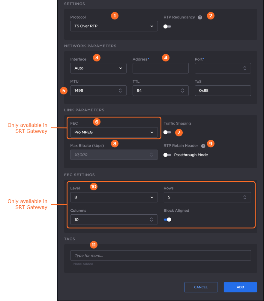
Select TS over RTP from the Protocol drop-down menu.
If SMPTE 2022-7 support is desired:
Toggle RTP Redundancy to ON.
Use the Add and – buttons next to each network address to add/subtract network paths when completing the following step.
Select the desired network interface to use for the output in the dropdown. Available options depend on the hardware configuration.
Enter the output address and port number.
Tip
An even-numbered port is required for RTP, as recommended in RFC 3550. (The next odd-numbered port is typically reserved for RTCP messages.)
Enter values for MTU, TTL, and ToS:
MTU (Maximum Transmission Unit) — The maximum allowed size of IP packets for the outgoing data stream. Range: 280-1500.
TTL (Time-to Live for stream packets) — The number of router hops the stream packet is allowed to travel/pass before it must be discarded. Range: 1-255.
ToS (Type of Service) — This value will be assigned to the Type of Service field of the IP Header for the outgoing streams. Range: 0x00-0xFF.
If you have a Haivision SRT Gateway, enable or disable PRO-MPEG Forward Error Correction (FEC).
Important
When PRO-MPEG is selected and Level A is selected in step 10, the next even numbered port following the port specified in Step 4 is allocated to the column FEC packets.
When PRO-MPEG is selected and Level B is selected in step 10, the two even numbered ports following the port specified in Step 4 are allocated to the column and row FEC packets, respectively.
Enable or disable Traffic Shaping for the stream. For some limited networks, such as satellites or some dedicated network pipes, it may be necessary to enable Traffic Shaping to smooth the traffic and respect the absolute upper limit configured. Traffic Shaping controls the outgoing stream so that the inter-packet time is constrained, to reduce the probability that TCP packets are dropped in a session.
Tip
Enabling Traffic Shaping does not dynamically modify the video encoder bitrate.
If traffic shaping is enabled in the previous step, enter the Maximum Bitrate in kbps.
(RTP Redundancy must be disabled) If you plan to tunnel an RTP stream through SRT and your original RTP stream has its respective Passthrough Mode toggle enabled, enable the Retain Header > Passthrough Mode toggle to use the original RTP headers for this output. See Tunnelling an RTP Stream Through SRT for more details.
For Haivision SRT Gateway, if PRO-MPEG FEC is enabled in step 6, enter the PRO-MPEG values:
Level — The level of FEC protection: A (Column only) uses the column FEC stream, or B (Row and Column) uses both column and row FEC streams.
Block Aligned — Specifies the type of FEC matrix scheme. Enable this toggle to align the FEC blocks in the matrix structure (i.e., sequential columns within a group start on the same row), see Annex C of SMPTE 2022-1. If disabled, the blocks are a staggered series of FEC packets (i.e., each column starts on the row below the row on which the previous column started), see Annex B of SMPTE 2022-1.
Columns — The number of columns in the FEC matrix.
Rows — The number of rows in the FEC matrix.
Optionally, assign tags to the output to help organize the Outputs list.
Click the Add button.
Note
For HLS outputs, the HEVC/H.265 codec is not supported. HEVC over HLS requires fMP4 segments, while HMG/HSG only supports MPEG-TS segments.
The following figure shows the available settings in the Add Output dialog for a TS over RTP output. The numbered callouts in the figure indicate the step number in this procedure.
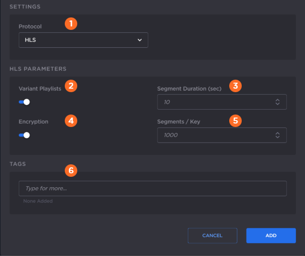
Select HLS from the Protocol drop-down menu.
Enable or disable HLS v4 Variant Playlists. If the output does not support variant playlists, disable this toggle.
Enter the maximum media Segment Duration (in seconds). A target duration of 10 seconds is recommended, and is the default if no target duration is specified. Shorter segments may increase network overhead for the client. Longer segments will increase broadcast latency and initial startup time.
Note
Apple strongly recommends a 10 second target duration (See this link). If you use a smaller target duration, you increase the likelihood of a stall. If you've got live content being delivered through a CDN, there will be propagation delays, and for this content to make it all the way out to the edge nodes on the CDN it will be variable. In addition, if the client is fetching the data over a cellular network there will be higher latencies. Both of these factors make it much more likely you'll encounter a stall if you use a small target duration.
Enable or disable HLS Encryption (AES-128 using 16-octet keys).
If HLS encryption is enabled, in Segments/Keys enter how often a new random key file is inserted. That is, a new random key file is inserted every n media segments (key rotation). Each group of n segments is encrypted using a different key.
Optionally, assign tags to the output to help organize the Outputs list.
Click the Add button.
Continue to Step 3 Create Route.