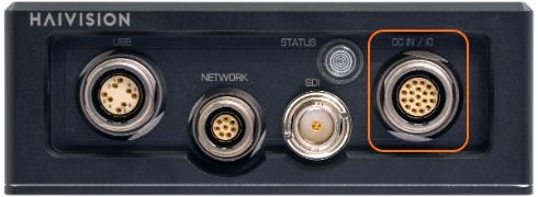
DC IN and I/O Connector
The following tables provide the manufacturer names, part numbers, and pinouts for the KX1 DC IN and I/O connector.
DC IN & I/O (Power, Audio & Serial) Connector | |||
|---|---|---|---|
 | On Unit | Mating Connector | |
Manufacturer | LEMO | LEMO | |
Connector Type | DC IN & I/O | DC IN & I/O | |
Part Number | HEP.2M.319.XLNP | FGP.2M.319.XLCT | |
For the connector and cable, see Power up the KX1.
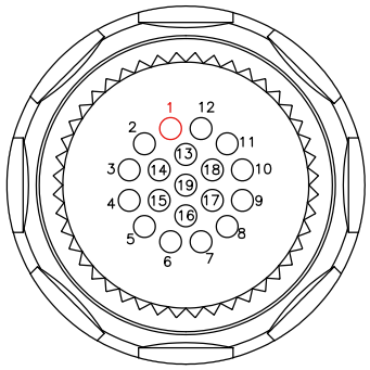
DC IN & I/O Connector Pinout (#HEP.2M.319.XLNP)
PIN # | Signal | RS-232 Connections |
|---|---|---|
1 | POWER IN +28VDC | |
2 | FORCE RECOVERY GND | |
3 | SERIAL COM 0 - TXD | |
4 | SERIAL GND | |
5 | AUDIO OUT LEFT - | |
6 | AUDIO OUT LEFT + | TXD |
7 | AUDIO OUT RIGHT + | |
8 | FORCE RECOVERY# | |
9 | AUDIO IN LEFT + | |
10 | AUDIO IN RIGHT + | GND |
11 | SYSTEM RESET GND | RXD |
12 | POWER IN GND (28VDC) | |
13 | POWER BUTTON GND | |
14 | SERIAL COM 0 - RXD | |
15 | SYSTEM RESET# | |
16 | AUDIO OUT RIGHT - | |
17 | AUDIO IN LEFT - | |
18 | AUDIO IN RIGHT - | |
19 | POWER BUTTON PWR BTN# |
Note
The COM1 pins are DTE (Data Terminal Equipment) which defines the direction of the signals (IN/OUT).
The COM1 pins are configured by default for Metadata mode but may be switched to Management mode (to connect to a computer for management of the encoder) using the metadata CLI command. The metadata command may also be used to select the transceiver mode for the metadata capture (i.e., RS-232).